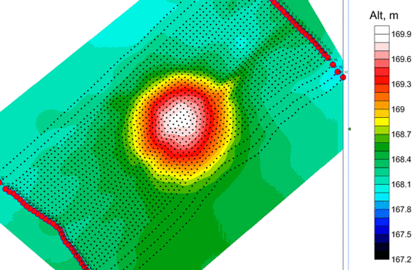
I also outline a number of additional workflows for users to be aware of and test the validity of the Revit Toposurface and a few of the caveats associated to this workflow. So, now that we understand the principle workflow for taking X, Y,Z Coordinate information from excelt into Revit for conversion to a native Revit Toposurface, we can delve into a little more detail on the overall process. Click the Green Arrow in the Modify|Edit Surface Contextual Tab to finish the Sketch. You will now see your Points information natively in Revit. Select your Unit Format (In the example below I use Meters) – press OK.

Next, Select the “Create from Import” dropdown arrow and click “Specify Points File”. Then, in Revit, go to the Masing & Site tab. Press Ctrl while you click and drag the anchor point to modify its placement.To Create a Revit Topographical Surface from Excel Coordinate (X,Y,Z) data, first ensure that the Excel Document is formatted so that the X,Y and Z Coordinates Fall into the First, second and Third Column respective (with no other additions). The anchor point location can be moved to another location for more accurate placement. The Move tool allows you to move the file using coordinate or x,y,z values of the destination's location. In some cases, the file may float above the ground, so ensure you zoom out to determine it if that is the case. Move to Display tool shifts the target Revit or CAD feature layer to the current display extent and places it on the surface of the ground by default. Once you have your area of interest, you can create a bookmark for that location. Locate tool to search for an area using keywords related to the approximate location where the file should appear in the view. This speeds up the process, and you can add the entire file once the georeferencing is complete.

When georeferencing a Revit file, add only a single feature class, such as Walls or Exterior Shell, and not the entire file. If it was not created in Revit or another CAD package with a proper coordinate system, choose one of the options to define where the file should appear in the map. If the drawing was given coordinate system information when it was created in an AutoCAD product, assign the appropriate projection and the CAD file will draw in the expected location.

To move a Revit model or CAD file, use theĭefine Projection tool on the Building tab.

To determine the units of the selected coordinate system, click Details and view Linear Units.


 0 kommentar(er)
